PT Deck Bridge Design
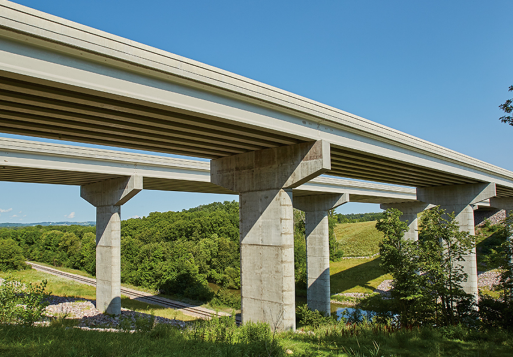
PT Deck Introduction
The shape of a post-tensioning deck can vary depending on the specific requirements of the bridge and the design preferences of the engineers. However, some common shapes include:
* Flat slab: This type of deck has a uniform thickness throughout its span and is typically used for shorter spans or where headroom clearance is a concern. Flat slab decks offer simplicity in construction and maintenance.

* Haunched slab: Haunched slabs feature a varying thickness, with the depth increasing towards the supports of the bridge. This design helps distribute the loads more efficiently and enhances the structural performance of the bridge, particularly for longer spans.

* Box girder: Box girders consist of a hollow box-like structure that provides excellent torsional stiffness and resistance to lateral forces. The deck is typically formed by the top slab of the box girder, which can be post-tensioned to improve structural efficiency and performance.
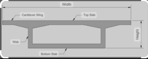
*Tapered or variable-depth deck: In this design, the deck thickness varies along the span of the bridge, with deeper sections near the supports and shallower sections towards the center. Tapered decks are often used to optimize material usage and structural efficiency while accommodating varying load distributions.
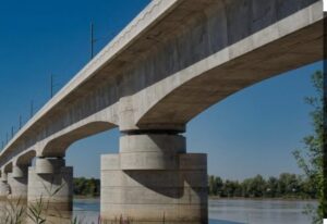
The shape of the post-tensioning deck is selected or based on factors such as span length, traffic loads, aesthetic considerations, and structural requirements, with the goal of achieving an optimal balance between performance, cost, and constructability.
Post Tensioning
One crucial aspect of bridge deck design is the post-tensioning system. This system involves applying tension to the steel tendons after the concrete has been cast, which increases the strength and durability of the deck. Through the use of a post-tensioning system, it is possible to minimize the amount of reinforcement required in the deck, thereby reducing the overall weight and cost of the structure. Initially trial profile of tendon is considered in longitudinal beam model of deck and stresses of deck are checked for quasi permanent load cases as per euro code 0 . For quasi permanent case, the deck should remain under compression with no tension allowed. This way using various trial-error approach, Tendon profile is achieved which satisfy the stress limits of deck and final PT profile is used in further longitudinal analysis .

Longitudinal Analysis
Another critical factor to consider in bridge deck design is the longitudinal flexure, which refers to the bending of the deck in the direction of traffic flow. To ensure that the deck can withstand the loads imposed by ULS and ALS combinations of basic loads, it is necessary to calculate the maximum flexural capacity along each beam element of deck in regular interval including critical sagging and hogging location of deck using in-house design spreadsheet or commercially available software such as “adsec” and compared them with ULS and ALS design Moments. Shear and torsion capacity are also evaluated at d/2 and 2d distance from face of bearing support and compared with design ULS /ALS shear /Torsion forces. Ensuring the flexure , Shear and torsional utilization within capacity, SLS stresses within the limits and crack width within specified limits as per design basis deck reinforcement is determined accordingly.
Transverse Analysis
To capture transverse load distribution of deck , a shell model is generated in FEA model with thickness of slab as per design and support location as per global model . Critical cases of vehicle load positioning on deck is considered along with Dead, SIDL loads and ULS , ALS and SLS cases are formed. Design forces are extracted and used further in design check of various part of deck slab under ULS and SLS condition and transverse reinforcement are determined accordingly.
PT Anchorage Design
PT cables are anchored at end cross beam and high compressive force is exerted on concrete surface behind anchor plate of PT cable. Therefore it requires additional checks for Bursting Tension , Spalling and equilibrium reinforcement near anchorage face. To determine these reinforcement strut and ties approach is used . 3d FEA model or Analytical methods are provided in various design codes such as Euro code or CIREA codes that can be used to determine bursting , spalling and equilibrium RC . Spiral RC are provided behind each PT anchor to resist the primary zone of bursting and close links are provided enclosing tendons up to certain specific distance from anchorage based on width and depth of girders as secondary zone of anchorage.
Design Drawings
Finally, the design is translated in to design drawings with sequence of key information’s organized in set of drawings such as general arrangement, elevation and sections of bridge showing overall dimension of deck, thickness of wearing coarse, drainage arrangement, concrete form drawings for deck , PT layout, RC detailing of all elements of deck along with substructure and foundation drawings.
In conclusion, designing a reliable and durable bridge deck requires careful consideration of various design, including post-tensioned design, longitudinal flexure, shear and torsion design, transverse design, stresses check, crack width check, and local anchorage checks and reinforcement detailing. By creating FEA model and conducting a comprehensive design analysis , it is possible to ensure that all these factors are taken into account and that the deck is designed to withstand the loads imposed by traffic, gravity and environmental loads.
